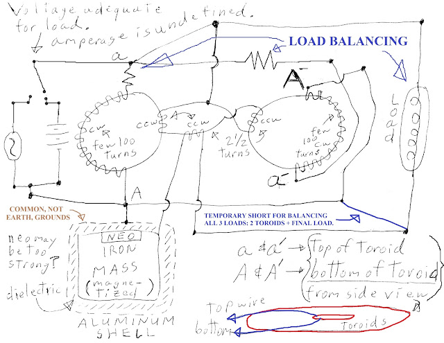
Towards the end of the video, up above, I mention that I needed to balance the load by replicating equivalent resistances twice more at each of the toroids so that all three match their resistances with each other. And I mentioned that this circuit is like an AC transmission line in which the top two horizontal paths for electricity (to travel along) are the transmission lines and the two toroids and the load at the far right are three shorts, or shunts, each of whose resistances must match each other if I'm to see the load's LED/s light up at all. Otherwise, all of the amperage will flow down both toroids and avoid traveling down the load's LED/s causing the LED/s at the power source – my little Sota Instruments AC Zapper – to light up, but nothing else indicating a short of some kind. Now, maybe this is the way it's supposed to be? Maybe all of the power is supposed to travel down each of the windings of both toroids and avoid the load's LED/s? I don't know..... Or, at least, this was what I thought before I started to, actually, build myself a circuit to test. That is when I discovered that I might be wrong, because this circuit is supposed to have various modes of operation not the least of which is whenever the two “grounded” voltage references, common or Earth grounds, are at zero state – which is where I'm at in the development of this circuit at the moment.
Now, there's an interesting thought which occurred to me as to what type of resistance should I have along each of these three locations.
What if I counterpoise two DC motors facing each other (in reverse polarity with respect to how their wirings are connected inline to each other) and surround them on either side with two diodes – each of whom are pointing towards the motors at their collective center? And this constitutes the parallel shunt across the two ends of each toroid's windings? Like this...
What if I counterpoise two DC motors facing each other (in reverse polarity with respect to how their wirings are connected inline to each other) and surround them on either side with two diodes – each of whom are pointing towards the motors at their collective center? And this constitutes the parallel shunt across the two ends of each toroid's windings? Like this...
The idea, here, is to collect electron "holes", Tesla's radiant energy, between the two diodes and process them into new electrons – within the magnetic fields of the two DC motors' windings – to serve as added amperage powering the circuit. Then, maybe the circuit won't need any “load balancing”?
BTW, Chuck C Stanley answered my question on how to respectively treat LEDs by keeping their amperage under 20 mA and between 1.8 to 2.2 V with a 220 ohm resistor.
BTW, Chuck C Stanley answered my question on how to respectively treat LEDs by keeping their amperage under 20 mA and between 1.8 to 2.2 V with a 220 ohm resistor.
I'm guessing that a pair of DC motors could be coupled in parallel with each toroid, surrounded by diodes pointing inwards, and a resistor could be added to each end of a toroid to match the total resistance across each motor/diode pair? Maybe this will do something interesting? Such as, boost the conversion of electron holes into electron flow within the confines of each toroid's magnetic field? I don't know... But I have to keep conjecturing or else give up development.
The axle of each motor is not hooked up to anything, but is allowed to spin freely.
What if it matters whether the frequency is low or high? I suspect that the choice for a mass of magnetizable material may rest upon this criteria resulting in iron for low frequencies (the last diagram, above) versus aluminum for high frequencies (the following diagram)...
Here is a post explaining why I think so...
Or better yet, maybe it's better to encourage high frequencies over low by positioning the aluminum as the core and making the iron a surrounding cover for the aluminum? Both substances are coated with a thin veneer of electroplated copper and an insulating space lies between them and the outside...
Or better yet, maybe it's better to encourage high frequencies over low by positioning the aluminum as the core and making the iron a surrounding cover for the aluminum? Both substances are coated with a thin veneer of electroplated copper and an insulating space lies between them and the outside...


No comments:
Post a Comment